Practical Electronics
Course Overview
Practical Electronics is designed to teach students the basic concepts of electricity and the equipment used. Throughout the duration of the class students will learn how to properly use and test circuits.

|
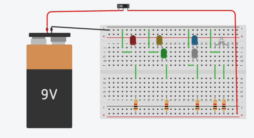
Simple Circuit The picture above shows different types of circuits using an breadboard. I connected the battery to opposite ends of the breadboard to organize the wires. The first circuit from left to right is a simple circuit. A simple circuit compiles of a power source and wires connecting to what you want outputted. In this case it is the LED. I also used a resistor in the process to not cause a short circuit. A short circuit is when the resistance on the components is lower than needed. I used the resistor to keep the voltage lower in each circuit.
Series Circuit The next circuit I created was a series circuit. A series circuit works in a way that uses both LEDs as a connector in the circuit. If one of the bulbs gets disconnected or stop working, the circuit will become open and it will not work anymore. The circuit needs both LEDs to be connected for the electron flow to be in motion.
Parallel Circuit The next circuit I created was a series circuit. A series circuit works in a way that uses both LEDs as a connector in the circuit. If one of the bulbs gets disconnected or stop working, the circuit will become open and it will not work anymore. The circuit needs both LEDs to be connected for the electron flow to be in motion.
Simple LED Circuit
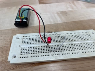
What? This circuit consists of a 9V battery, a battery snap, a LED, and a 100 Ohm resistor. How? It is connected together using a breadboard. This would still be classified as a simple circuit. The 9V battery provides power throughout the circuit. The LED brightness depends on what type of resistor is put on it. The more current allowed to go through the system the brighter it becomes. Why? I believe it is important to start on a simple circuit to figure out the basics of putting together electrical components. Potentiometer Circuit
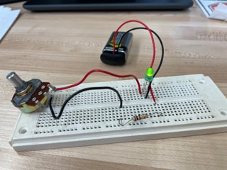
What? This circuit was the same circuit as before but with a potentiometer. The potentiometer was put in place of the connecting wire and acted as a control device. How? I put this together with a breadboard again and experimented with the potentiometer to figure out what it does and how it does it. The potentiometer basically works like a resistor the can vary how much resistance it has. Why? I believe this is important to my knowledge so I can better understand what a potentiometer does and what it is used for. |

|
|
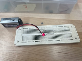
Photocell Circuit
What? This circuit used a component called a photocell which detects light and adjusts the current accordingly, to power the LED. The photocell controls the resistance it has according to how much light it detects. Therefore, in turn controlling the current. How? There are different types of photocells with the most recognizable ones being in a night light or automatic light poles. This photocell however works along the lines of the more light detected, the brighter the LED gets. I learned this by covering the photocell so that is detected no light and the LED went dim. Why? This is important to my knowledge so I know how to make a lighting circuit that depends on how much light is detected. |
|

|
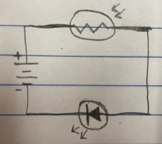
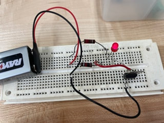
Capacitor Circuit
What? This circuit is a parallel circuit that has a capacitor and an LED. There are two resistors used in this circuit to prevent each individual component from overloading and causing a short circuit. How? The capacitor works as a secondary storage of electrons. It is a backup power source with a very limited time it can supply energy to a load. Once the original power source is taken out of the circuit it will start supplying energy to the load until it is out. This circuit needs to be a parallel circuit in order for it to works because it needs to stay connected to the load. Why? This information is important in order for me to build something that needs a secondary power source incase the first one ever goes out. Not this capacitor but ones with a larger storage of electrons can be useful in something like a refrigerator or freezer if there is a power outage. It is a short time that it can maintain but it can be necessary in appliances that need to stay on. |

NPN Transistor

PNP Transistor
Ammeter
Volt meter
Ohm meter


Solar Cell Circuit

Thermocouple Circuit
|
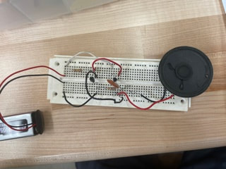
Speaker Circuit
What? This circuit only has three components needed. It consists of a battery, a 10 ohm resistor, and a speaker. The circuit is not closed because the speaker only makes sound when there is a sudden change in voltage. In turn it will only make the sound when the connection is made or broken. How? A speaker has a coil of wire in it and when an electrical current is sent through the coil of wire, it makes a magnetic field. This interacts with the magnetic field of the permanent magnet attached to the speakers. This causes the magnet to move back and forth. This motion is the thing that creates the sound waves we hear. This is why Alternate Current is needed for this process because Direct Current can't change direction therefore not giving the back and forth motion that is needed. Why? This lab was important because it is good to get familiar with the speaker since people use them everyday. It is also good to be able to make a circuit that has multiple components that can do multiple things at once. Diode Circuit
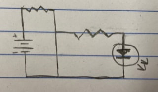
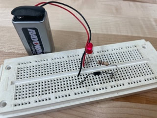
What? This circuit has 4 components making it up. A battery, a Diode, a resistor, and a Led. The current goes through the negative wire (black) through the diode into the resistor then through the LED an back into the positive wire (red). How? A diode works as a sort of one way road. Current can only flow through it in one direction. If I were to flip the diode around in the opposite direction the circuit would not work. A diode would classify as a semiconductor. Why? This is important to my knowledge because if I ever a, using alternating current in a circuit and do not want the electron flow to go a certain way. I could use a diode allowing the current to pass through in one direction but not the other. SCR(Thyristor) Circuit
What? This circuit is made of multiple components. A battery, two resistors with different resistances, a LED, and a SCR. How? A Silicon-Controlled Rectifier or SCR is basically a diode from the previous circuit but it has an extra terminal called a gate. This gate is used to trigger the circuit into flowing completely. The way to trigger the gate to open is to send a positive current through it. The current does not need stay connected to the gate for the circuit to work. As long as it is applied for any amount of time, the circuit will stay one from there on out unless another connection is broken. Why? I believe this is important to my knowledge because if I am working with a medium or high voltage I could use the SCR when I need to control when the voltage is applied into the circuit. NPN and PNP Transistor Circuit
What? These circuits are made of multiple components. A battery, two resistors, two LEDs, a push button, and a transistor. How? An NPN transistor works like an electronic switch. It can be turned on and off. To turn a transistor on you need a certain amount of voltage flowing through the circuit. A transistor has three legs, a base, a collector, and an emitter. Current can go either from the base to the collector or from the emitter to the collector. If a small current flows from base to emitter it allows a larger current to flow from collector to emitter. A PNP Transistor isn't too different from a NPN transistor. The main difference between them is that the current flows in the opposite direction because the polarity is flipped. Why? It is important to my knowledge to know how a transistor works so I know how to use a smaller circuit with a smaller voltage to control a much bigger circuit with a higher voltage. They also can be used together in a circuit to control the direction of the current. Transistor Oscillator Circuit
What? This circuit is composed of a battery, two resistors, a capacitor, a NPN transistor, a PNP transistor, and a speaker. How? Using a PNP and NPN transistor in a circuit, I could simulate alternate current. The transistor fight with each other and create an oscillating effect to that the speaker has a constant output of sound. This is due to the fact that they have opposite polarities. Why? This is a useful circuit to know because if I needed to change direct current to alternate current to make a speaker work or to just keep a constant changing output. Multimeter Usage
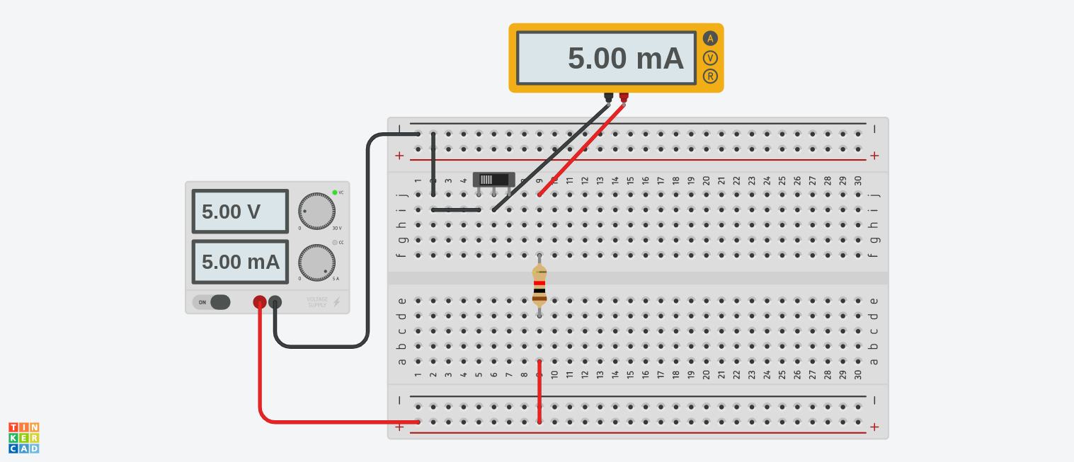
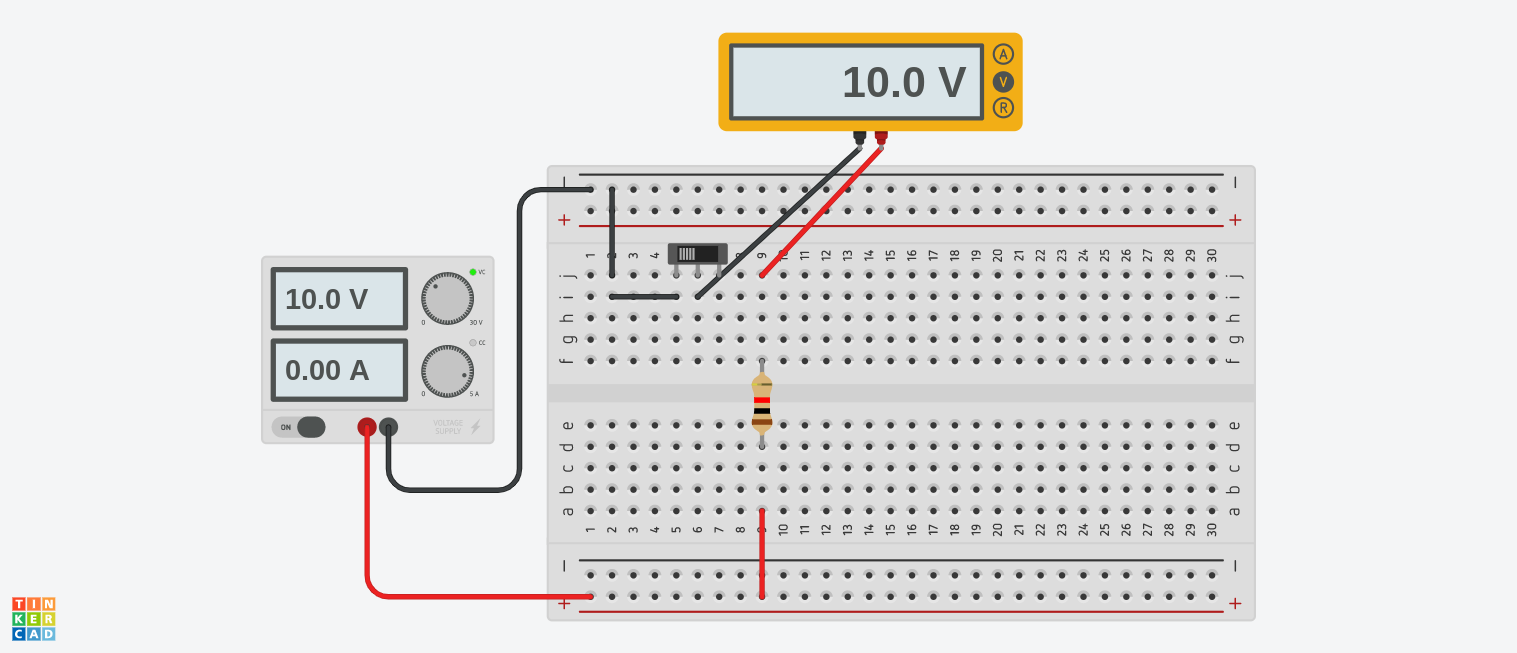
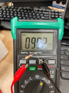
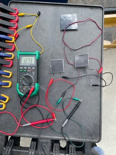
What? A Multimeter is a device that measure Voltage, Current, and Resistance. The circuits on the left have 4 components. A power supply on the far left, a slide switch, a resistor, and a Multimeter all connect using a breadboard. The first multimeter is measuring 5 milliamps. To put it in perspective 100 milliamps or 0.1 amp could be fatal. The other circuit is measuring 10 volts. How? Notice how in the first circuit is showing that there is 5 volts coming from the power supply but in the second circuit it is showing that there is only 10 volts and 0 amps. This is because amps need volts so the current can flow but volts do not need amps to flow. Its easy to understand if you imagine this as a stream. Volts would be the pressure of the water and amps would be the direction in which the water is flowing. The water needs pressure in order to flow in a stream. The same concept applies in electricity. Amps needs volts to keep the current flowing. The last picture represents an Ohm meter. Ohms are the opposition to the current flow in an electrical circuit. What the meter is measuring is a 100 ohm resistor with a +/- 5% tolerance. The +/- 5% tolerance means that it could be as low as 95 ohms or up to 105 ohms. To know what resistance a resistor has, you have to know how to read one. All resistors are color coded according to the sheet down below. To work an ohm meter, unlike the other two, you have to separate the component from the circuit that you want to measure. This is because the meter actually sends its own current through the component. Even though the resistor only is 99.2 ohms it will still be labeled as a 100 ohm resistor due to the tolerance talked about previously Why? The importance of this lab is so that I can understand how to measure the quantities that I need to be in a circuit and so that I can use a power supply so manipulate how much of those quantities I need. It is also important to know how electricity work when working with it. You shouldn't go in blind when working with something that could kill you. 
Ammeter Continued
What? This is the same circuit as shown previously in the last lab. Dude to the fact that an Ammeter is more difficult to use in a circuit I am going to go into more detail. To recap, an Ammeter is used to measure the current flow in a circuit, otherwise known as amperes or amps. How? An Ammeter needs to be hooked in a circuit in series. As you remember a series circuit is when you hook every component in a line. If one of the components gets disconnected, the circuit will become open. An Ammeter needs to be connected in series so that all the current in a circuit goes through the meter. If this is not the case and hooked in parallel, it will cause a short circuit and may blow the fuse in the Ammeter. This is because an Ammeter has a low internal resistance. Why? This lab is very important to know because when you need to measure the current output of a circuit, you'll need to know how to properly and safely set up an Ammeter. Due to its low internal resistance it is very easy to blow a fuse in an Ammeter. A Very Simple Circuit
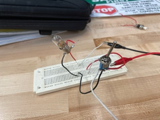
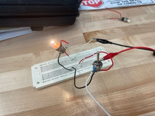
What? This circuit is as simple as you could make. It only has two components. A 6v incandescent light bulb and a 9v battery. How? The way this circuit works is as simple as you can get. The electrons flow out from the negative terminal in the battery, up through the wires and into the light bulb. The current travels through the light and heats up the coil on the inside of the glass to the point where is lights up. Then the current goes down through the posite wire and goes through the positive terminal in the battery thus providing a complete path throughout the circuit. For the current to flow it needs to have a closed circuit which is when the circuit is fully connected. If there is a break in the circuit it will then become an open circuit due to the opening. Why? It is important to know a simple circuit so that you can have the basics down and be knowledgeable of how a circuit works. This helps to create more complex circuits. If a circuit is perhaps not working, it could just be a break in the system. You should always check your connections to make sure they are all in. Sources of Electricity
What? The two circuits to the left are a solar cell circuit and a thermocouple circuit. These are different types of load that can be used to power a circuit. How? The top circuit is a solar cell circuit. A solar cell can transform the light of the sun and make it into electrical energy. This causes a current to flow through the circuit. One solar cell of these type only have about a 4 volt maximum output. I put three in one circuit and is produced 12.73 volts with them. This goes off the came concept of solar panels. The more light that is absorbed the more voltage the circuit will have. The bottom circuit has what is called a thermocouple. It changes heat into electricity. To test it out I used a light to heat up the end of the thermocouple and connected the multimeter to measure it. Depending on how much heat is put on the end of the thermocouple, it could go from 0 to around 3 volts. After holding the lighter on it for about 5 seconds it reached its max at 3.01 volts. Why? Knowing different types of power sources can help to make an easier way to supply a circuit with power rather than using a traditional method. For example, when you want a light to turn on when the sun is out, you could use a solar cell to have it only get power when it is sunny rather than needing a static battery with a photocell. Sources of Electricity
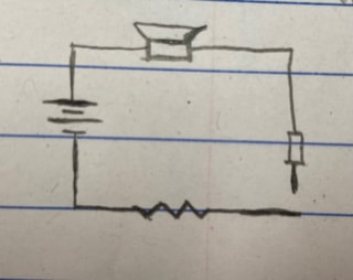
What? This circuit is a simple circuit. The circuits components consist of a power supply, a SPST switch and an incandescent light bulb. The current goes through the negative terminal of the power supply, through the light bulb, into the switch and through the positive terminal of the power supply. How? There is multiple different types of switches. There is a Single Pole Single Throw (SPST), Single Pole Double Throw (SPDT), Double Pole Single Throw (DPST), Double Pole Double Throw (DPDT), Push Button Normal Open (PBNO), and Push Button Normal Closed (PBNC). A throw is when the switch has a connection point between terminal 1-6. There can be multiple connections in a switch to control different parts in a circuit. The connection point that get thrown are called poles. Why? This is important to know so that you can make a circuit that has a switch to turn on and off different outputs. This could completely change the function of a circuit. 
|

|
|
Lab 2.8 Switching Circuits
What and How? This lab went through different types of switches and how to use them in a circuit. The first circuit you see here is a Double Pole Double Throw(DPDT) switch. The circuit changes which light is on depending on how the switch is thrown. This switch makes each light independent to each other. If one light were to be disconnected the other will still work. It negates the need to connect the lights together. The next switch is a three way switch. This type of circuit is commonly used in household lighting. The way this works is that when the switches are thrown in the same direction the light will turn on. If they are thrown opposite to each other the light turns off. This is usually found when there is a light for stairs. There will be a switch at the top of the stairs and one at the bottom. This makes it more accessible to use that light. The next switch is a Double Pole Single Throw(DPST) switch. It works on the same principle as the DPDT switch seen before. It changes which light turns on depending on how the switch is thrown. This switch is essentially a more simplified switch than the first example. The nex switch is personally my favorite switch of this lab. It is another Double Pole Double Throw(DPDT) switch but with a twist. Notice how in the first picture the lights are dimmer than they are in the second. This is because this switch is wired so that the circuit can go between series to parallel and vice versa. The first picture the switch is parallel. You can tell this because the voltage drop gets evenly distributed to each light. When the switch is thrown the circuit turn into series and gets brighter since the voltage drop decreases. Why? This lab is very important because a switch is an essential part in a circuit as a control. Depending on the wiring, you can completely change the the function and use of the circuit. The switch can make or break the circuit. Literally. Burglar Alarm Project
What? For this project the goal was to make a buzzer that can be portable and functioning correctly. As you can see on the bottom left picture, we used a circuit board to connect all the components together. I used a slide switch to turn the circuit on and off and two push buttons to activate the buzzer. Once the buttons are pushed the buzzer will turn on and stay active until the circuit is turned off with the slide switch. How? I used the circuit board to solder all of my components together to make a working circuit. The slide switch controls the connection to the battery pack, meaning that it either opens the connection and turns the circuit off, or closed the connection and keeps it on. I used one Push Button Normally Closed (PBNC) and one Push Button Normally Open (PBNO). This is so that when one of the activate, it keeps the electricity flowing if the other were to get disconnected. I used a drill press to make holes into the box so that the buttons could stay still and be accessible when the box is closed. I used a dremel tool to cut the opening for the slide switch with the same idea in mind. I then drilled smaller holes so that I could use screws to mount the battery pack, circuit board, and slide switch on the box. I then made holes above the buzzer so when activated, it would be louder. Why? This project was important to my knowledge because it showed me how to plan out a circuit, how to use a circuit board, and how to make it a portable device. All in all it was one of my favorite circuits to make in the class. |


Class Takeaways
Overall I was completely satisfied with this class and it taught me a lot about the trade of electricity. It taught me valuable lessons that I can use one day. I would recommend this class to anyone that is interested in getting into electricity.
Overall I was completely satisfied with this class and it taught me a lot about the trade of electricity. It taught me valuable lessons that I can use one day. I would recommend this class to anyone that is interested in getting into electricity.
